Planar Chromatography
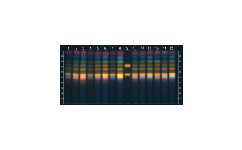
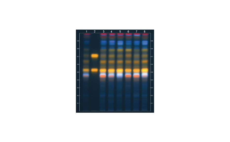
Planar chromatography is a form of liquid chromatography: A liquid mobile phase dissolves the substances of a mixture and transports them through a flat (planar) stationary phase. Different affinities of substances to the two phases afford separation as they cause different retardation with respect to the velocity of the mobile phase. In column chromatography, this affects the time of elution (retention time) while in planar chromatography the position of substance relative to the front of the mobile phase on the plate is changed. Because planar chromatography takes place in a developing chamber, also a gas phase is established, which can influence the separation. There are two forms of planar chromatography: Paper Chromatography and Thin-Layer Chromatography (TLC). Planar chromatography is performed in off-line mode, which means that the principle steps of the process (sample application, development, derivatization, detection, evaluation) are independent in time and location. This leads to some specific advantages:
- great flexibility in the choice of stationary and mobile phases
- parallel analysis and visual comparison of multiple samples and standards
- single-use of the stationary phase reduces the need for sample clean-up
- possibility of multiple detections without the need to repeat chromatography
- convenient chemical derivatization of separated substances and detection of biological activity
- low cost
- rapid
The Thin-Layer Chromatography (TLC) System
The TLC system comprises the mobile phase, stationary phase, and gas phase. The first two phases interact directly with the sample components and achieve their separation. The gas phase is established in the developing chamber and affects the dry part of the stationary phase.
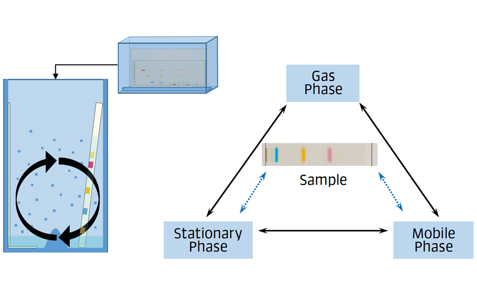
Figure 1: The TLC system
The Stationary Phase
Different adsorbents can be used as stationary phase in TLC but silica gel (in normal phase mode) is the most common one. Due to its porous (6 nm) structure, silica gel has a large surface featuring siloxane and silanol groups. These can interact with different functional groups of the sample components based on polarity, acidity and non-specific interaction. Silica gel is a strong adsorbent and interacts with water from the lab atmosphere. This process affects the activity and the selectivity of the stationary phase.
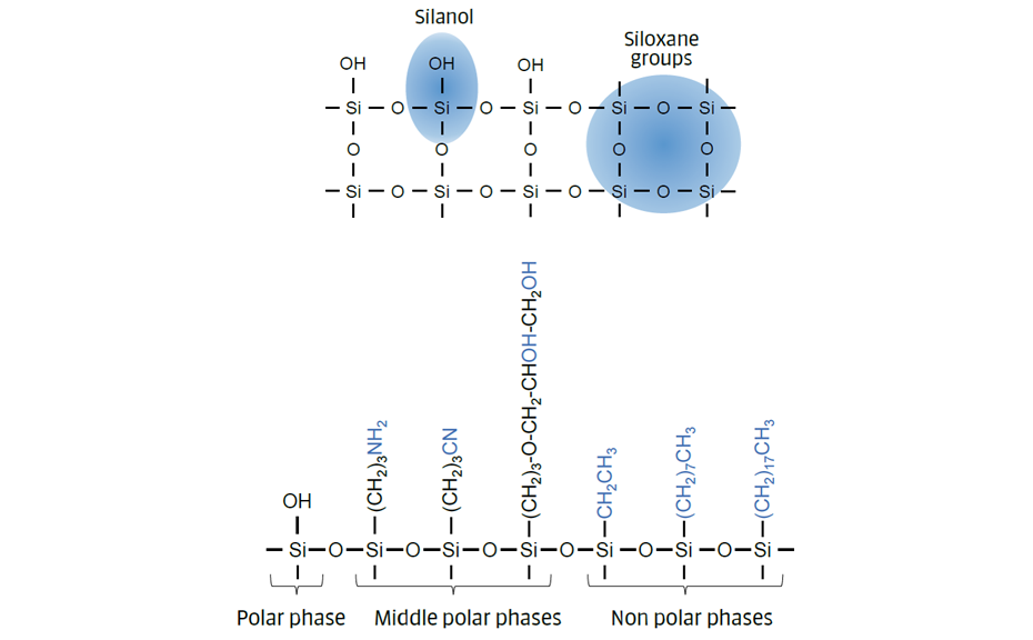
Figure 2: Stationary phases (based on silica gel)
Chemical modification of the silanol groups leads to bonded phases, of non-polar (reversed-phase – RP) or polar (normal phase – NP) nature and quite different selectivity.
|
Name (Merck) |
Functionality |
Polarity |
Principal use as |
|---|---|---|---|
| RP 2 (C2) | Dimethyl | Non-polar | RP (partition) |
| RP 8 (C8) | Octyl | Non-polar | RP (partition) |
| RP 18 (C18) | Octadecyl | Non-polar | RP (partition) |
| Silica gel (SiOH) | Silanol | Polar | NP (adsorption/partition) |
| Amino (NH2) | 3-aminopropyl | Middle polar | RP/NP (partition/adsorption) |
| Cyano (CN) | 3-cyanopropyl | Middle polar | RP/NP (partition/adsorption) |
| Diol (OH) | Spacer bonded propanediol | Middle polar | NP (adsorption) |
For non-polar reversed-phases, polarity decreases and hydrophobicity increases with the chain length (C2 > C8 > C18). The dominant retention mechanism is partition: the analytes are distributed between the bonded (liquid) phase and the mobile phase. Plates labelled “wettable” (W) are compatible with higher amounts of water in the mobile phase.
The dominant retention mechanism on normal phases is adsorption: the analytes and the molecules of the mobile phase compete for adsorption on the stationary phase.
Practical tip: on silica gel, the RF values decrease with the number and increasing polarity of the functional groups: hydrocarbons (low polarity) usually migrate to a higher RF with a medium- polarity mobile phase. In contrast, acids, alcohols or sugars (higher polarity) tend to stay closer to or at the application position with a medium-polarity mobile phase. On a reversed-phase, the longer the analyte’s carbon chain, the lower its RF values (higher retention).
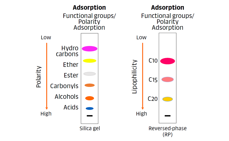
Figure 3: The dominant retention mechanisms for normal phases (adsorption) and non-polar reversed-phases (partition).
To create a stable adsorbent layer on the support, most commercial plates contain an organic polymeric binder. Some plates have a so-called fluorescence indicator that is excited at a specific wavelength, e.g. short wave UV (254 nm), labeled as F254.
| F | fluorescence indicator |
| 254 | excitation wavelength for F |
| PSC/PF | preparative layer chromatography, thickness > 0.25 mm |
| RP 2, 8, 18 | reversed-phase with chain length/C-atoms 2, 8, 18 |
| W | water resistant / wettable layer (most common for RP-18 plates) |
| s | acid stable indicator |
| 60 | average pore diameter in Angstrom (60 Å = 6 nm) |
| AMD | automated multiple development, thickness ~ 0.1 mm |
| MS | mass spectrometry, thickness ~ 0.1 mm |
| G | gypsum (used as binder) |
The Mobile Phase
The mobile phase is the solvent or mixture of solvents that transports the analytes through the stationary phase and contributes to the selectivity of the chromatographic systems.
Note: mobile phase and developing solvent are not the same thing. The mobile phase is the liquid that migrates through the stationary phase. Its composition (proportion of solvents) may change during chromatography due to evaporation and other factors. The developing solvent has a defined composition and is filled into the developing chamber.
The solvent strength refers to the ability of the solvent to elute the solutes from the stationary phase. By increasing the mobile phase strength, the retention of the solute decreases and the RF value increases. In adsorption chromatography, solvent strength is commonly called “polarity”, while in reversed-phase, it can be expressed as lipophilicity. A classification of solvent strength (Polarity index P’) for normal phase separation is shown in the table below.
|
Solvent |
Polarity index P' |
Selectivity Group |
|---|---|---|
| Hexane | 0.0 | - |
| Heptane | 0.1 | - |
| Isopropyl ether | 2.4 | I |
| Diethyl ether | 2.8 | I |
| 2-propanol | 3.9 | II |
| n-butanol | 3.9 | II |
| 1-propanol | 4.0 | II |
| Ethanol | 4.3 | II |
| Methanol | 5.1 | II |
| Tetrahydrofuran | 4.0 | III |
| Acetic acid | 6.0 | IV |
| Dichloromethane | 3.1 | V |
| Ethyl acetate | 4.4 | VI |
| Methylethyl ketone | 4.7 | VI |
| Dioxane | 4.8 | VI |
| Acetone | 5.1 | VI |
| Acetonitrile | 5.8 | VI |
| Toluene | 2.4 | VII |
| Benzene | 2.7 | VII |
| p-xylene | 2.5 | VII |
| Nitromethane | 6.0 | VII |
| Chloroform | 4.1 | VIII |
| Water | 10.2 | VIII |
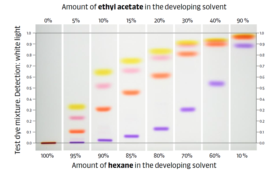
Figure 4: Illustration of the effect of increasing mobile phase strength on the RF values of a dye mixture on silica gel. The more ethyl acetate (P’ of 4.4) is in the mobile phase, the higher the RF of the zones.
In reversed phase chromatography, the solvent strength increases with the increasing amount of organic modifier and decreasing amount of water.
The mobile phase selectivity describes the interaction of the solvent with different sample molecules. R. L. Snyder proposed eight solvent selectivity groups with different properties (Figure 6). Solvents from different selectivity groups can have the same polarity (e.g. tetrahydrofuran and 1-propanol). This can affect the migration order of analytes in a sample.
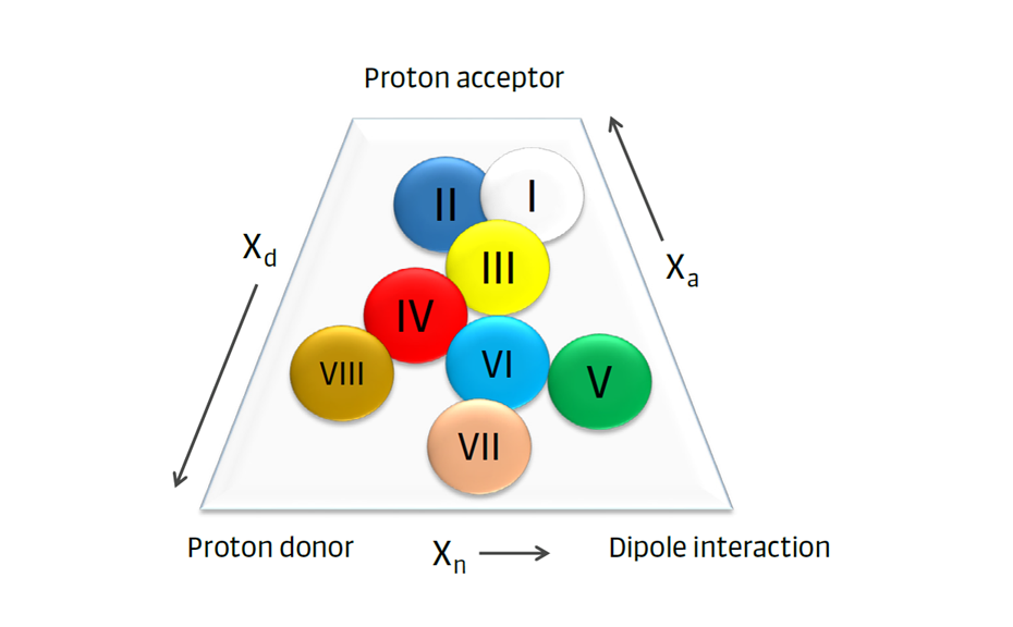
Figure 5: Eight solvent selectivity groups with different properties
In the practical example shown in Figure 6, a test dye mixture was analyzed with four different developing solvents of the same strength on silica gel. The solvents in cases (a) and (b), ethyl acetate and acetone, belong to group VI, causing very similar migration orders, except for the purple zone. By changing to a solvent from group II (1-propanol), the yellow and blue zones switch positions, and the gray zone has a lower RF value (case c). In the last case (d), with neat chloroform (group VIII), nearly all zones change positions.
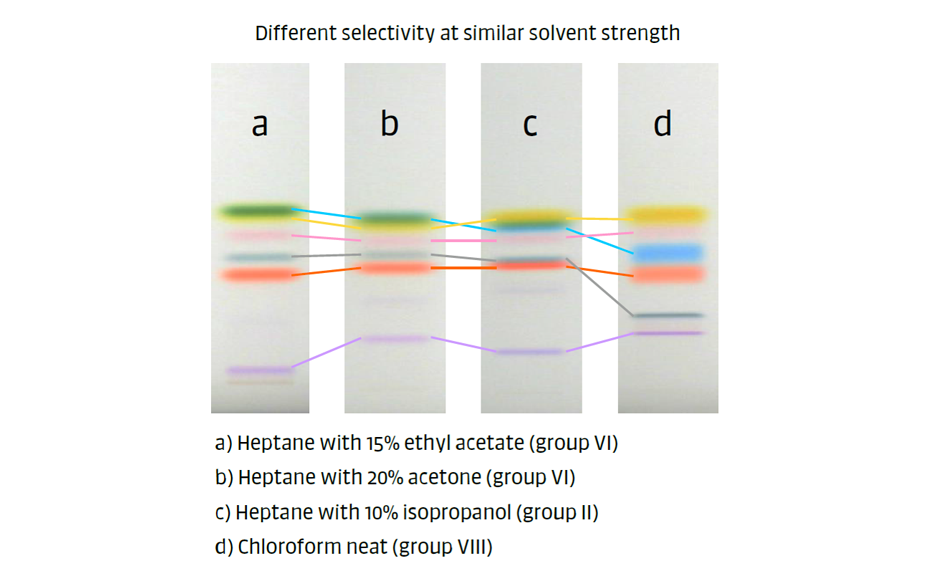
Figure 6: Analysis of test dye mixture with four different mobile phases of the same strength on silica gel.
The Gas Phase
A feature that distinguishes TLC from other chromatographic techniques is the presence of an additional gas phase. It is formed in the chromatographic chamber by evaporation of solvents. The gas phase interacts with the stationary and mobile phases, before and during chromatography. It is possible to standardize the conditions of the gas phase in order to achieve reproducible results.
In a “classic TLC chamber”, i.e. a twin-trough chamber (TTC) with specific dimensions, containing filter paper, a developing solvent, a stationary phase with samples, and which is closed with a lid, the gas phase is involved in four important processes:
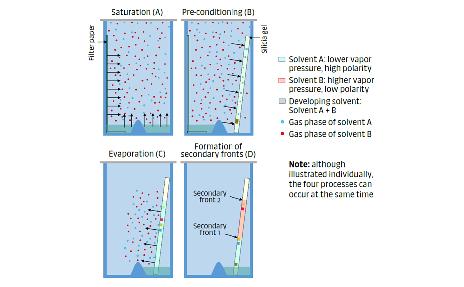
Figure 7: The gas phase is involved in four important processes: saturation (A), pre-conditioning (B), evaporation (C), and secondary fronts (D).
- Saturation (Figure 7A): The components of the developing solvent evaporate and eventually establish phase equilibrium with their vapor (e.g. after 20 minutes, when using a filter paper to increase the surface for evaporation). The vapor pressure of the individual components of the developing solvent affects the composition of the gas phase.
- Pre-conditioning (Figure 7B): The components of the gas phase are adsorbed on the dry stationary phase, forming a thin layer of solvent molecules. A polar solvent in the gas phase will interact more with the silica gel than one of lower polarity.
- Evaporation of the mobile phase during chromatography (Figure 7C): During the development step, a part of the mobile phase may evaporate from the wet stationary phase, leading to increased developing time, particularly if the chamber has not been saturated.
- Secondary fronts (Figure 7D): During the development step, an active stationary phase can separate the components of the mobile phase, resulting in the formation of secondary fronts that may influence the separation of the analytes. This effect is weaker with chamber saturation and pre-conditioning of the stationary phase.
In TLC, separation usually takes place in a partial equilibrium between stationary, mobile, and gas phases.
The Retardation Factor
The retardation factor (RF) in planar chromatography, also known as the retention factor, is a term used to describe the relative positions of zones in the chromatogram. It is calculated based on the ratio of the distances traveled by the center of a zone “A” (b) and distance traveled by the mobile phase front (a) with respect to the application position.
By definition, RF values are always less than one, and they are displayed with two decimals. IUPAC defines hRF as RF multiplied by 100, but most pharmacopoeias and publications use RF.
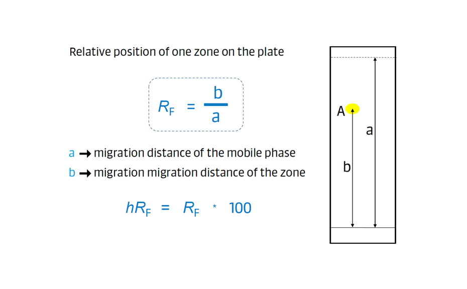
Figure 8: Calculation of the retardation factor (RF)
TLC vs. HPTLC
Thin-layer chromatography (TLC) is a special case of planar chromatography. TLC has been used since the mid-20th century for diverse separation purposes, and until now, it is generally done either manually or with a simple instrumental setup. It is a simple, flexible, and rapid tool for qualitative investigations. However, as there is no agreement on a standardized TLC methodology, it is challenging to get reproducible results between laboratories (if that is the method’s aim).
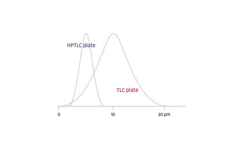
The term High-Performance Thin-Layer Chromatography (HPTLC) was introduced when plates with smaller particle sizes and dimensions were brought to the market. HPTLC is considered the evolution of classical TLC. With time, HPTLC was clearly defined by compendia and became a concept that prioritizes the quality and reproducibility of the results. The HPTLC concept includes:
- HPTLC glass plates of fixed dimensions (20 x 10 cm) with layers of silica gel (or other adsorbents) with particle sizes between 2 and 10 μm and a fluorescence indicator;
- Simple to sophisticated instruments, available for all chromatography steps;
- HPTLC software;
- Well-defined methods with optimized and standardized parameters;
- Qualified data through method specific system suitability test (SST);
- Validated methods, compliant with cGxP;
- Traceable digital data.
A standardized and optimized TLC method on a 20 x 20 cm plate can be scaled down to run on a 20 x 10 cm HPTLC plate. Thus, HPTLC can be considered as miniaturized TLC.
The main differences between TLC and HPTLC are shown in the table below:
|
TLC |
HPTLC |
|
|---|---|---|
| Principle | Planar chromatography | Planar chromatography |
| Primary focus | Simplicity, low cost | Reproducibility, separation power |
| Process | Flexible, no rules | Highly standardized methodology/optimized parameters |
| Methods | Only a few parameters defined | Well defined and validated |
| Flexibility | Very high | None for validated methods, high between methods |
| Target | Rapid, preliminary results | Reliable analytical results |
| Data structure | Simple chromatograms/photographs | Traceable digital images/scan data qualified by system suitability test (SST) on each plate, cGMP compliant reporting |
| Samples/references | Side by side on the plate | On the same or on different plates |
| Plate | TLC any format | HPTLC 20 x 10 cm |
| Instrumentation | None to simple | Simple to sophisticated |
| Cost | Very low | Medium to high compared to TLC, low per sample compared to HPLC |
